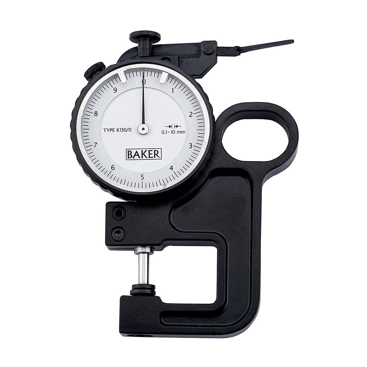
Baker 2.4 - 23.6 inch Crankshaft Web Deflection Gauge, CS2
Roll over the image to zoom in

Key Features
- Product Type: Thickness Gauge
- Type of Product: Crankshaft Gauges
- Range (Inches): 2.4 - 23.6 inch
- Graduation: 0 - 20
ToolBuy Benefits
- Secure Payments
- Order Tracking (opens in a new tab)
₹8,524 (Incl. of all taxes)
₹7,224 + ₹1,300 GST (18%)
MRP was MRP ₹8,810
Save 18%
2 Business Days
1
–
Download Product LeafletNot available
Download Baker CatalogueNot available
Download Baker CatalogueNot available

Highlights
Excessive web deflection is dangerous for the engine. The cause may be faulty or damaged crankshaft, damaged bearing, poor bearing alignment, excessive bearing clearance or slackness, faulty flanging to transmission, flywheel or Vee Belt pulley, etc.
Features:
- Every gauge carries a calibration certificate giving actual values
- Crankshaft Gauge measures the Web deflection of a crankshaft
- The BAKER Crankshaft Gauge is developed to identify and avoid the problems mentioned above
- The Gauge covers web-to-web distance of 60-600 mm
- Supplied in a sleek wooden box
- Gauge contacts are pointed & fit into dimples in the webs. A heavy spring pressure ensures that the Gauge is restrained but is free to turn in relation to the crankshaft.
- An adjustable balance weight restrains the Gauge against the rotation of the crankshaft so that the dial always faces the inspector
How To Use Baker Crankshaft Gauge:
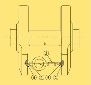 Determine the distance (a) between two Webs. Assemble the extension (2) and fixed gauging point (3) and screw this assembly into the threaded bush of the dial gauge unit opposite to live point (1). Overall length from tip of fully extended live point (1) to tip of fixed point (3) should be about 1 to 2 mm greater than web distance (a) |
| The back of the dial Gauge unit takes the balance weight to keep the dial facing upward while the Gauge is suspended between the webs during Crankshaft rotation. Use center bush for horizontal upward position and outer bush for inclined upward position. Without balance weight, the indicator adopts a face down position |
| Place the Gauge between webs of Crankshaft so that gauging points are located in punch holes (4), center punched where measurement of deflection is required. First, place spring loaded live point (1) in one of the two punch holes (4), then locate fixed point (3) in other punch hole |
| Set dial pointer to 20 on (metric) dial by rotating the indicator bezel. Turn Crankshaft by hand & observe pointer movement on dial |
| Read deflections at various positions of the crankshaft revolution as set out in manufacturer’s inspection procedure |
Please Note that Product may differ eg. colour, size from the product Image displayed on website. Kindly check the specifications provided to make better purchase decision. M.R.P Prices and specifications are subject to change without notice.
Specifications
| Type of Product | Crankshaft Gauges |
|---|---|
| Range (Inches) | 2.4 - 23.6 inch |
| Reading | 0.0005 inch |
| Graduation | 0 - 20 |